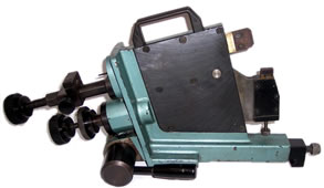
 To obtain a superior finish on a crankshaft journal, all available equipment must be used to support the journal as it is being ground. Besides the headstock and tailstock, which are used to secure the crankshaft in the grinding machine, a steady rest and its shoes are used. If you look to the image to your left, you will see the side view of a Winona Van Norman steady rest and the shoes that come into direct contact with the crankshaft. Although the Winona Van Norman model pictured to the left does not have a dial indicator, most models accept this precision measuring device as an accessory.
When grinding the rod journals, a steady rest is typically positioned to the side of the oil passage and tightened down to the grinding machine’s ways. Since the shoes ride directly on a journal, they must avoid the oil passage as a shoe may be drawn into the hole and damage the crankshaft and/or the equipment being used. Also, there must be adequate room for the operator to use the Arnold gauge to measure the amount of material being ground off. Especially on V6 crankshafts, where there is little side to side clearance, placing tooling and measuring devices on the journal at the same time can be quite a challenge. Once properly positioned, safely to the side of any oil passages and with plenty of room for the Arnold gauge, the automotive machinist then slowly tightens up the steady rest so that it supports the journal as it is being ground. As the machinist takes off more material, the arms are slowly tightened even more so that shoes remain snug to the journal throughout the entire grinding process. The steady rest is the one tool that resists the force created from the grinding wheel as it is slowly fed into the journal, which is an important function to produce finished journals of the proper size and microfinish. Continue reading
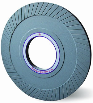 Most automotive machine shops will have a small assortment of grinding wheels available, with varying widths, so that they may grind narrow V6 journals and wide V8 journals. For industrial crankshafts, which normally have a 1/8” radius or larger, a wheel is normally reserved specifically for these types of industrial grinding operations. You may view a typical crankshaft grinding wheel by looking to the picture at your left. Although the face of this wheel is mostly used for grinding, you will see that the sides have directional grooves. These grooves help to grind thrusts or to grind additional side to side clearance in main or rod journals that have been
 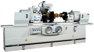 To grind a crankshaft, one obviously needs the equipment to get the job done. A crankshaft grinding machine is used for this operation, and it closely resembles the appearance of a lathe. Just like a lathe, the crankshaft grinding machine (pictured left) has chucks, a headstock, a tailstock and ways which they may be accurately positioned on. The noticeable difference between a crankshaft grinding machine and lathe is that the grinder has a large
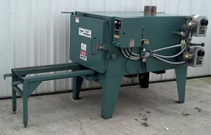
 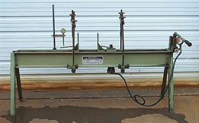 Many automotive machine shops use a hydraulic press (pictured left) to straighten crankshafts. This is accomplished by placing the crankshaft in v blocks and applying pressure on the crankshaft journal, on the opposite side of the bend, to essentially bend the crankshaft back into its normal position. This process can be more difficult on cast steel crankshafts as they are more likely to crack under pressure. To avoid the potential of cracking, some shops apply heat to the center main journal to help it relax so that it goes back into its natural position with less force. 4340 forged steel crankshafts, for example, are less likely to break when using a hydraulic press to correct the bend since this type of steel is much softer than cast steel.