One of the most common machining operations performed on crankshafts is grinding. By grinding the rod and main journals, the bearing surface of the crankshaft can be repaired to provide a great foundation for a rebuilt engine. Below you will learn more about angle grinder and the grinding process, which is detailed from an ASE certified engine machinist.
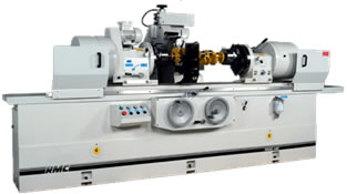 To grind a crankshaft, one obviously needs the equipment to get the job done. A crankshaft grinding machine is used for this operation, and it closely resembles the appearance of a lathe. Just like a lathe, the crankshaft grinding machine (pictured left) has chucks, a headstock, a tailstock and ways which they may be accurately positioned on. The noticeable difference between a crankshaft grinding machine and lathe is that the grinder has a large grinding wheel and the chucks may be offset to accommodate a crankshaft’s connecting rod stroke.
The crankshaft grinding wheel is secured with a hub, balanced and mounted to the machines arbor to accommodate operation at high RPMs. The surface finish on most grinding wheels is 54 grit, which is a similar specification as used for sandpaper. The most common grinding wheels accommodate an arbor size of 3”, 5” and 8” for industrial applications. Grinding wheels, when new, typically measure 22” in diameter and can weigh approximately 50 lbs.
The type of grinding wheels used to grind crankshafts is determined by the size of the journals to be ground and the Rockwell hardness of the crankshaft’s material. In most cases an all-purpose wheel is sufficient to grind those crankshafts that have a hardness rating of 35 RC or less (ie. cast iron and forged steel). Another consideration that the automotive machinist takes into account when grinding a crankshaft is the size of the radius. Most automotive machine shops have multiple wheels available that accommodate both a standard 3/32” and 1/8” radius, with a 3/32” radius being more commonly used on OEM passenger car crankshafts.
When grinding a crankshaft, the automotive machinist almost always sets the machine’s chucks up for the stroke of the crankshaft to be ground first. This stroke is determined by measuring the centerline of the main journal to the centerline of the rod journal and multiplying that distance by a factor of two, by consulting a reference manual or with the assistance of a stroke gauge. Since the crankshaft will be positioned off the centerline of the mains, and rotating within the machine, this offset must be counterbalanced with weight. The crankshaft grinding machine has weights that may be adjusted, on both the headstock and tailstock, to accommodate the offset.
With the stroke and weights visually set, the snout of the crankshaft is secured in the headstock chuck and the seal surface or rear flange is secured in the tailstock. Once the crankshaft has been secured in the machine, an indexing gauge is used to position the first connecting rod to be ground. Once positioned, a dial indicator is used to dial-in the journal so that it has very little runout and runs true when rotated completely around. At this time a steady rest is attached to the ways of the machine to stabilize the journal in preparation for the grinding process.
With the first connecting rod journal properly set, and the machine running, the operator then brings the wheel into the journal to be ground. The machine has a rapid feed lever to perform this operation, and it is important that the operator has backed up the manual adjustment a hundred thousandths of an inch or greater. At such time the machinist can gradually bring the wheel into the journal that is to be ground and activate the coolant lever. The coolant not only helps to keep the journal cool as it is being ground, but it also removes the debris created from the grinding process. As the wheel comes into contact with the journal, the operator slowly feeds the wheel in while manually adjusting the steady rest so that it continually maintains a slight amount of pressure on the journal to resist the pressure created from the grinding wheel. In most cases, the machinist will leave .003” for the finish cut.
 Measuring the material being taken off of the journal is accomplished with an Arnold gauge. This gauge gently slips over the journal and has a precision needle that may be set to 0 or the finish size desired. To determine what the finish size is, the operator must set the gauge after using a micrometer to measure the journal. Once set, the Arnold gauge may reliably be used to grind all of the journals that have the same finish diameter.
There are two ways that an automotive machinist may grind journals. Plunge grinding refers to bringing the wheel into the journal to its finish size, with no side to side movement. The second grinding method used is called sweep grinding, which takes the journal to its finish size and moved horizontally across the journal so that its entire surface is swept while at the finish size. Plunge grinding can often lead to steps on a journal while sweeping the journal is more likely to produce taper. Since neither of these conditions are desired, it is important that the headstock and tailstock of the grinding machine be true before any machining occurs.
With the first connecting rod journal completed, the operator may then remove the steady rest and position it for the next connecting rod journal to be ground. The operator then may release the chucks and index the crankshaft over to the journal to be ground by using the steady rest as a stop. Most steady rests have a built in gauge that allows the operator to slightly adjust the stroke so that minor adjustments can be made. Once indicated in, this journal and all other connecting rod journals are ground in the same way as previously noted.
When all of the connecting rod journals are ground, the crankshaft is removed from the grinding machine and set aside so that the operator can bring the machine’s stroke and counterweights to their neutral position. Once the machine is setup to grind the main journals on the centerline, the crankshaft is once again secured in the machine with the headstock and tailstock. The automotive machinist then indicates both the snout of the crankshaft and the furthest part of the crankshaft (normally the rear main seal or flange) so that they both run true with no runout. The steady rest is then positioned on the center main journal and the journal is ground to its finish size in the same manner as the connecting rods were ground. When grinding the mains, the steady rest is not moved from journal to journal as is performed on the rod journals. It will remain in the center to support the crankshaft as the other mains are ground.
Once the crankshaft has been completely ground, it is then ready to be chamfered and polished. The chamfering and polishing process will ensure that all burs created from grinding the crankshaft are removed from the oil passages and that the crankshaft’s journals achieve a sufficient microfinish to accommodate new engine bearings.
It is our hope that the information on this page will help you to better understand the crankshaft grinding process. If you found this information useful, please consider rating this page below.
 (1 votes, average: 5.00 out of 5)
![]() Loading...
Loading...